
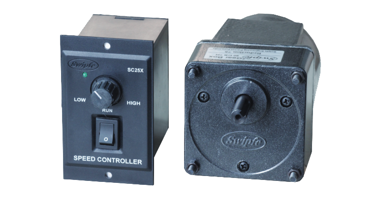
Speed Control Motor
25 Watt
Square Flange
80mm x 80mm
Motor Specifications:
| Model | Supply | Frequency Hz |
Stall Torque
Nm |
Rated Torque Nm |
Rated Speed RPM |
Rated Current Amp |
Capacitor μF |
|---|---|---|---|---|---|---|---|
| 5SX440 | Single Phase 230V | 50 | 0.34 | 0.28 | 1350 | 0.27 | 2 |
| 5SY440 | Three Phase 230V | 50 | 0.56 | 0.28 | 1350 | 0.25 | - |
| 5SY440 | Three Phase 415V | 50 | 0.69 | 0.28 | 1400 | 17 | - |
| 5SX240 | Single Phase 230V | 50 | 0.20 | 0.14 | 2800 | 0.26 | 1 |
| 5SY240 | Three Phase 230V | 50 | 0.22 | 0.14 | 2800 | 0.23 | - |
| 5SY240 | Three Phase 415V | 50 | 0.33 | 0.14 | 2850 | 0.16 | - |
Indicates type of Shaft, G - Gear, R - Round, F - Frame, C - Custom
Gear Motor Torque Table:
The maximum permissible torque is 20 Nm
No Load speed of Motor at 50Hz is approx. 1440RPM
50Hz
Unit : N.m
| RPM | 480 | 400 | 288 | 240 | 192 | 160 | 115 | 96 | 80 | 57 | 48 | 40 | 29 | 24 | 19 | 16 | 14 | 12 | 9.6 | 8 |
|---|---|---|---|---|---|---|---|---|---|---|---|---|---|---|---|---|---|---|---|---|
| Gear Ratio | 3 | 3.6 | 5 | 6 | 7.5 | 9 | 12.5 | 15 | 18 | 25 | 30 | 36 | 50 | 60 | 75 | 90 | 100 | 120 | 150 | 180 |
| Output Torque | 0.72 | 0.87 | 1.2 | 1.4 | 1.8 | 2.2 | 2.7 | 3.2 | 3.9 | 4.9 | 5.8 | 7.0 | 8.8 | 10.6 | 13.3 | 15.9 | 17.7 | 20.0 | 20.0 | 20.0 |
The Gear Boxes are sold Seperately.
A coloured background indicates gear shaft rotation in same direction as motor shaft.
A white background indicates gear shaft rotation in opposite direction to the motor shaft.
The speed of geared motor is calculated by dividing motor's no load speed by the gear ratio.
The actual speed is less than the displayed value, depending upon the load.
Characteristics, specifications and dimensions are subject to change without notice.
Motor Dimensions:
Motor, Gearbox with Terminal Box


Motor Round Shaft with Terminal Box


Motor, Gearbox with Lead Wires


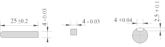
Key & Keyway
Max. Weight:
Motor - 2.2 kg
Gear Box - 1.5 kg
Wiring Diagram:
Wiring Diagram for Single Phase Motor
Short Black wires and connect as shown to rotate
the motor in clockwise direction.
To change the direction, flip CW to CCW.
Red wires are for running winding & Black wires are for starting winding. To change the direction, interchange Black wires or Red wires.
Wiring Diagram for Three Phase Motor
Star Connection
To change the direction, interchange any two wires between U, V & W. For 415 Volt 3 Phase supply, wires are connected as shown. Short White, Black, & Blue wires and then insulate it properly.
Delta Connection
To change the direction, interchange any two wires
between U, V & W.
For 230 Volt 3 Phase supply,
wires are connected as shown.
Change the direction of motor only after it stops rotating. If the attempt is made during rotation, motor may not change the direction or change the direction after some time.