
Electromagnetic Brake Motor
180 Watt
Square Flange
90mm x 90mm
Continuous Rating with Frequent Start Stop,
Load Holding & Minimum Overrun.
Electromagnetic Fail Safe Brake (Power Off
activated)
Fitted at the Back of Induction Motor.
Rotates in Clockwise or Counter Clockwise Direction.
Terminal Box or Lead Wires for Connection.

Motor Specifications:
| Model | Supply | Frequency Hz |
Stall Torque
Nm |
Rated Torque Nm |
Rated Speed RPM |
Rated Current Amp |
Capacitor μF |
|---|---|---|---|---|---|---|---|
| 5EX4180 | Single Phase 230V | 50 | 1.45 | 1.22 | 1350 | 1.10 | 7 |
| 5EY4180 | Three Phase 230V | 50 | 1.50 | 1.34 | 1250 | 0.90 | - |
| 5EY4180 | Three Phase 415V | 50 | 1.94 | 1.22 | 1350 | 0.48 | - |
| 5EX2180 | Single Phase 230V | 50 | 0.75 | 0.61 | 2700 | 1.10 | 4 |
| 5EY2180 | Three Phase 230V | 50 | 0.66 | 0.61 | 2600 | 0.90 | - |
| 5EY2180 | Three Phase 415V | 50 | 1.10 | 0.61 | 2700 | 0.51 | - |
Indicates type of Shaft, G - Gear, R - Round, F - Frame, C - Custom
Gear Motor Torque Table:
The maximum permissible torque is 20 Nm
No Load speed of Motor at 50Hz is approx. 1440RPM
50Hz
Unit : N.m
| RPM | 480 | 400 | 288 | 240 | 192 | 160 | 115 | 96 | 80 | 57 | 48 | 40 | 29 | 24 | 19 | 16 | 14 | 12 | 9.6 | 8 |
|---|---|---|---|---|---|---|---|---|---|---|---|---|---|---|---|---|---|---|---|---|
| Gear Ratio | 3 | 3.6 | 5 | 6 | 7.5 | 9 | 12.5 | 15 | 18 | 25 | 30 | 36 | 50 | 60 | 75 | 90 | 100 | 120 | 150 | 180 |
| Output Torque | 3.4 | 4.1 | 5.7 | 6.8 | 8.5 | 10.2 | 12.8 | 15.3 | 18.4 | 20.0 | 20.0 | 20.0 | 20.0 | 20.0 | 20.0 | 20.0 | 20.0 | 20.0 | 20.0 | 20.0 |
The Gear Boxes are sold Seperately.
A coloured background indicates gear shaft rotation in same direction as motor shaft.
A white background indicates gear shaft rotation in opposite direction to the motor shaft.
The speed of geared motor is calculated by dividing motor's no load speed by the gear ratio.
The actual speed is less than the displayed value, depending upon the load.
Characteristics, specifications and dimensions are subject to change without notice.
Motor Dimensions:
Motor, Gearbox with Terminal Box


Motor Round Shaft with Terminal Box


Motor, Gearbox with Lead Wires


Key & Keyway

Max. Weight:
Motor - 4.5 kg
Gear Box - 1.7 kg
Wiring Diagram:
Wiring Diagram for Single Phase Motor

When SW1 is switched ON, Electromagnetic Brake is released & motor starts rotating. When SW1 is switched OFF then electro- magnetic brake will be applied stopping the motor immediately & holding the load.
Apply voltage on the orange brake lead wires only, to release the Electromagnetic Brake.
To change the direction of rotation, flip CW to CCW.
Wiring Diagram for Three Phase Motor (Delta Connection)

When SW1 is switched ON, electromagnetic Brake is released & motor starts rotating. When Swl is switched OFF then electro- magnetic brake will be applied stopping motor immediately, holding the load.
Apply voltage on the orange brake lead wires only, to release the Electromagnetic Brake.
To change the direction of rotation, interchange any two wires between U, V & W.
Wiring Diagram for Three Phase Motor (Star Connection)

Supply power to the motor and electromagnetic brake simultaneously. When power is supplied to the Electromagnetic Brake (orange wires), the brake is released and the motor is enabled for rotation.
When power is switched OFF, the Electromagnetic Brake is applied, stopping the motor immediately and holding the load.
Apply voltage only to the orange brake lead wires to release the Electromagnetic Brake.
To change the direction of rotation, interchange any two wires between U, V and W.
The brake is rated for 230VAC 1Ph or 24VDC
For brakes rated at 230VAC 1Ph, the supply must be connected through the rectifier supplied with the motor.
For brakes rated at 24VDC, the supply must be connected directly to the orange brake wires.
Make sure that power is supplied to both the motor and brake simultaneously. Brake will be released only after supply is given to brake part, enabling motor to rotate. The motor will not rotate and instead heat up causing it to burn if power supply is given only to the motor part and not to the brake part.
Change the direction of the motor only after it has completely stopped. Changing direction during rotation may cause delayed or improper operation.
Protection of contact (switch). If a switch is used for starting/stopping the motor or changing rotation direction, connect a CR circuit (commonly known as a Snubber Circuit) across the contacts for surge suppression and contact protection.
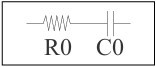
R0 = 5 Ω to 200 Ω
C0 = 0.1 µF to 0.2 µF, 1kV rating