
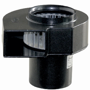
Centrifugal Blower
240 CFM
Impeller Ø 120 × 55 mm
Continuous Rating.
Aluminium Motor Body MS Casing.
Counter Clockwise Aluminium Impeller.
Blower Specifications:
| Model | Supply Voltage | Frequency Hz |
Rated Current Amp |
Rated Speed RPM |
Max Air Flow CFM |
Capacitor μF |
||
|---|---|---|---|---|---|---|---|---|
| Pa | mm of H2O | |||||||
| CB1255X | Single Phase 230V | 50 | 0.25 | 2700 | 240 | 285 | 29 | 1 |
| CB1255Y | Three Phase 415V | 50 | 0.16 | 2700 | 240 | 285 | 29 | - |
Centrifugal Blowers move air by means of the centrifugal force generated by rotating cylindrical impeller.
Used for applications where increased air pressure, increased static pressure, high airflow is required.
Centrifugal blowers have a small outlet, which concentrates air in a single direction, and are therefore suitable for local cooling.
Air Flow Vs Static Pressure:

Blower Dimensions:

 Max. Weight: 4.2 kg
Wiring Diagram:
Wiring Diagram for Single Phase Blower
Ensure that the impeller is rotating in counter clockwise direction. Airflow is maximum.

Short Black wires and connect as shown to rotate
the motor in counter clockwise direction.
To change the direction, connect the supply wire
from White to Red.
Wiring Diagram for Three Phase Blowerr

To Change the direction, interchange any two wires between U, V &W. For 415 V 3 Phase supply, wires are connected as shown. Short White, Black & Blue wires & then insulate it properly.

To change the direction, interchange any two wires between U, V & W.
For 230 V 3 Phase supply, wires are connected as shown.